

What Is A Drawing Of The Movement Of Material, Product, Or People?
Many dissimilar types of cartoon tin be used during the process of designing and constructing buildings. Some of the more commonly-used types of drawing are listed below, with links to articles providing farther information.
Run into besides: Video overview of different types of drawings.
And: Types of projection.
[edit] As-built drawings and record drawings
On building projects, it is common for changes to be made during construction considering of circumstances that emerge on site. As a effect, it is common for as-built drawings to be prepared, either during the construction process or when construction is complete, to reflect what has actually been built.
The contractor volition generally mark upwards changes to the 'final construction upshot' drawings on-site using red ink, and these can and so be used past the consultant team to create record drawings showing the completed project.
For more information run across: As-built drawings and record drawings.
[edit] Associates drawings
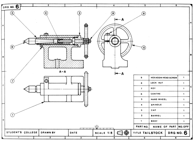
Associates drawings tin can be used to represent items that consist of more than i component. They show how the components fit together and may include, orthogonal plans, sections and elevations, or three-dimensional views, showing the assembled components, or an exploded view showing the relationship between the components and how they fit together.
For more data see: Assembly drawing and Exploded view.
[edit] Block programme
Block plans usually show the siting of a project in relation to Ordnance Survey Maps. Conventions are used to draw boundaries, roads and other details. Depending on the size of the projection, recommended scales are:
- 1 : 2500
- 1 : 1250
- 1 : 500
For more than data, run across Cake plan.
[edit] Component drawings
By and large, components are 'self-contained' and sourced from a unmarried supplier, typically the complete unit provided past that supplier rather than its constituent parts. Component drawings provide detailed data nigh the private units. They may exist fatigued at large scales such as; one:ten, 1:five, i:2, 1:i, then on. They may include data such as component dimensions, construction, tolerances, and and so on.
For more than information come across: Component drawing.
[edit] Concept drawings/sketches
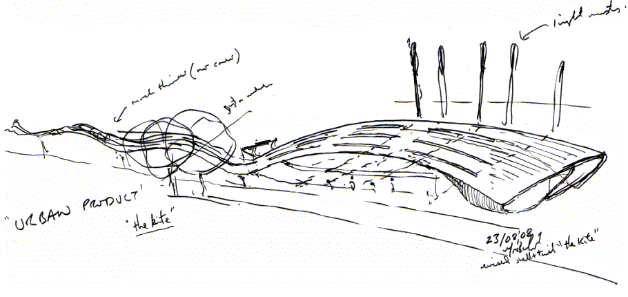
Concept drawings or sketches are drawings, frequently freehand, that are used as a quick and unproblematic way of exploring initial ideas for designs. They are not intended to be accurate or definitive, merely a way of investigating and communicating design principles and artful concepts.
For more than information see: Concept drawing.
[edit] Construction drawings/working drawings
Working drawings or construction drawings provide dimensioned, graphical information that can exist used; by a contractor to construct the works, or by suppliers to fabricate components of the works or to assemble or install components. Along with specifications and bills of quantities or schedules of piece of work, they form a part of the 'product information', that is prepared by designers and passed to the construction team to enable a project to be constructed.
For more information see: Construction drawing and working cartoon
[edit] Blueprint drawings
Design drawings are used to develop and communicate ideas almost a developing design. In the early stages they might merely demonstrate to the client the ability of a detail design team to undertake the design. They may so be used to develop and communicate the brief, investigate potential sites and assess options, develop the approved idea into a coherent and co-ordinated blueprint, and and then on.
For more than information come across: Blueprint drawings.
[edit] Detail drawings
Detail drawings provide a detailed description of the geometric form of a part of an object such as a building, span, tunnel, machine, plant, and and so on. They tend to be large-scale drawings that show in detail parts that may exist included in less detail on general arrangement drawings.
For more information see: Item cartoon.
[edit] Electrical drawing
An electric drawing, also known as a wiring diagram, is a type of technical drawing that provides visual representation and data relating to an electrical system or circuit. They are used to convey the technology design to the electricians or other workers who will use them to help install the electrical system.
For more information, run across Electrical drawing.
[edit] Elevations
The term 'elevation' refers to an orthographic project of the outside (or sometimes the interior) faces of a building, that is a 2-dimensional cartoon of the building'south façades. As buildings are rarely uncomplicated rectangular shapes in plan, an meridian drawing is a commencement bending project that shows all parts of the building equally seen from a detail management with the perspective flattened. Generally, elevations are produced for four directional views, for instance, n, s, east, west.
For more information run across: Elevations.
[edit] Floor plans

Floor plans are a form of orthographic projection that can exist used to evidence the layout of rooms within buildings, as seen from above. They may be prepared as office of the design process, or to provide instructions for construction, ofttimes associated with other drawings, schedules, and specifications.
For more information meet: Floor plan.
[edit] Applied science drawing
An engineering drawing is a type of technical drawing used to ascertain the requirements for engineering science products or components. Typically, the purpose of an applied science drawing is to clearly and accurately capture all geometric features of a product or component and then that a manufacturer or engineer tin can produce the required item.
For more information see: Engineering drawing.
[edit] Location drawings/full general system drawings
General system drawings (GA's, sometimes referred to equally location drawings) present the overall limerick of an object such as a building. Depending on the complexity of the building, this is likely to require a number of different projections, such as plans, sections and elevations, and may be spread across several different drawings.
For more than data run across: General arrangement drawing.
[edit] Installation drawings
Installation drawings present the information needed by trades to install part of the works. This may be particularly important for complex installations such every bit found rooms, data centres, ventilation systems, underfloor heating, and then on.
For more data run across: Installation cartoon.
[edit] Location program
A location plan is a supporting document that may be required by a planning authority every bit part of a planning application. A location plan provides an illustration of the proposed development in its surrounding context.
For more data, run into Location plan.
[edit] Perspective
Perspective drawing is a technique for depicting 3-dimensional volumes and spatial relationships based on the eye level and vanishing point (or points) of the viewer. It can requite a realistic impression of what a book or infinite will await like in reality.
Constructing perspective drawings of buildings is extremely complicated, but has been much simplified recently past the development of computer aided design (CAD), edifice information modelling (BIM) and other forms of computer generated imagery (CGI).
To find out more about perspective, see: The origins of perspective.
[edit] Production cartoon
Production drawings illustrate how to manufacture a product, providing information about dimensions, materials, finishes, tools required, methods of assembly and then on. They are used as instructional reference documents by workers and their supervisors on the store floor or product line to manufacture the products required.
For more information meet: Production drawing.
[edit] Scale cartoon
Scale drawing is a generic term used to describe any drawing that illustrates items at less than (or more than than) their actual size. This is generally necessary where the items is then big or small that information technology is not useful or convenient to draw information technology at its actual size.
For more information meet: Scale drawing.
[edit] Section drawings
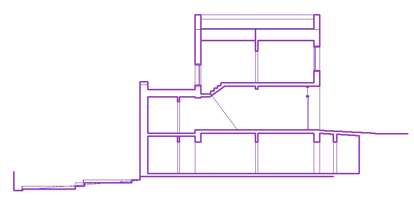
A section drawing shows a view of a construction as though it had been sliced in half or cutting forth another imaginary plane. This can be useful every bit it gives a view through the spaces and surrounding structures (typically across a vertical plane) that can reveal the relationships between the different parts of the buildings that might not be apparent on plan drawings.
For more information encounter: Section drawings.
[edit] Shop drawings
Shop drawings might be prepared by contractors, subcontractors, suppliers, manufacturers or fabricators. They generally relate to pre-fabricated components, showing how they should be manufactured or installed. They accept design intent drawings and specifications prepared past the project design squad and develop them to show in detail how the component will actually be manufactured, fabricated, assembled or installed.
For more information run across: Shop drawing
[edit] Site plans
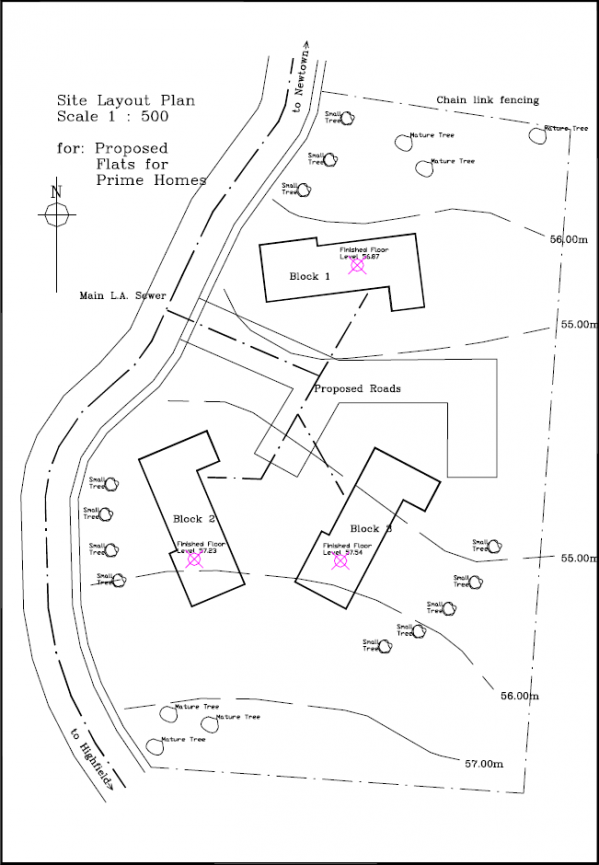
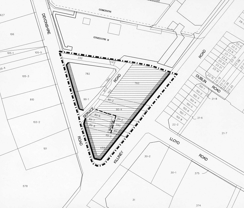
A site programme is a big-scale drawing that shows the full extent of the site for an existing or proposed evolution. Site plans, along with location plans, may be necessary for planning applications. In most cases, site plans volition be drawn upward following a serial of desk studies and site investigations.
For more information see: Site plan.
[edit] Technical drawings
The term 'technical drawing' has a very broad meaning, referring to any drawing that conveys the way that something functions or how information technology is constructed. Technical drawings are intended to convey one specific meaning, every bit opposed to artistic drawings which are expressive and may exist interpreted in a number of ways. Most drawings prepared during the design and construction of buildings might exist considered to be technical drawings.
For more data encounter: Technical cartoon.
[edit] Other types of drawing
- Title program.
- Builders' work details.
- Manufacturers' drawings
[edit] Other meanings
The word 'drawing' tin can also refer to: 'Mechanised methods of extracting a cylinder or, more ordinarily, a sheet of glass from a cook. Sheets were drawn from tank furnaces using equipment that gripped a layer of drinking glass as it started to solidify.' Ref Archaeological Show for Glassworking, Guidelines for Recovering, Analysing and Interpreting Evidence, published by Celebrated England in 2022.
[edit] Related manufactures on Designing Buildings
- Construction drawing.
- Working drawing.
- Detail drawing.
- Flooring plan.
- Blueprint drawings.
- As-built drawings and tape drawings.
- Section drawing.
- Scale cartoon.
- Site layout plan.
- Symbols on architectural drawings.
- Applied science cartoon.
- General arrangement drawing.
- Elevations.
- Technical cartoon.
- Product drawing.
- Site plan.
- Shop drawings.
- Title plan.
- Types of projection.
- Concept drawing.
- Component drawing.
- Visualisation.

Source: https://www.designingbuildings.co.uk/wiki/Types_of_drawings_for_building_design
Posted by: bockmartyart49.blogspot.com
0 Response to "What Is A Drawing Of The Movement Of Material, Product, Or People?"
Post a Comment